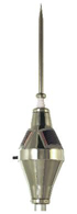
Satelit 3
The Early Streamer Emission Lightning ConductorIncluding TeleTesting supervision
The latest lightning protection solution developed by Duval Messien uses state-of-the-art technology incorporated in the Early Streamer Emission
lightning conductor Satelit 3 . This third generation of the Duval Messien ?Satelit? range uses this technology to force the lightning strike to follow a predetermined path towards the earthing system.
As opposed to a Simple Rod Lightning Conductor, the Satelit 3 concept consists of polarising the lightning conductor tip with a voltage of between 35kV and 45 kV, synchronised with the progress of the descending tracer, and of triggering an anticipated start for the ascending tracer.
Being always at the leading edge of technological advances, with its Satelit 3
Duval Messien is once again offering a ground-breaking development by introducing a remote system testing facility: the TeleTester-S3, thus providing a truly remarkable lightning protection solution with the Satelit 3 system.
The Satelit 3 range comprises three models with different performance characteristics: the Satelit 3-25, the Satelit 3-45 and the Satelit 3-60.
Satelit 3 :A NEW LIGHTNING CONDUCTOR CONCEPT
In accordance with the procedure detailed in the French standard NF C 17-102 dated July 1995, the range of lightning conductors has been the subject of indepth research and numerous tests in internationally recognised approved laboratories.
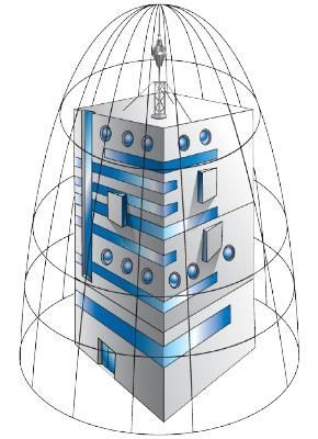
? Satelit 3 has been designed around a 304L quality stainless steel shell in order to guarantee high resistance to impacts, corrosion and chemical agents (hydrocarbons, acids....). It is perfectly suited for installation in chlorinated environments, in high humidity climates or in exposed industrial sites.
? The electronic components selected for the Satelit 3 are completely protected inside an inert resin block. The spark gap, made of solid stainless steel, is designed to conduct currents greater than 180 kA.
? The Satelit 3 is powered by a NI-MH type battery, continuously recharged by three indestructible, flexible solar cells, specially developed for Duval Messien. The heated encapsulation process used in manufacturing them ensures excellent tightness as well as improved protection against damage. The faces of each cell are made of Ethylene Tetra Fluoro-Ethylene (ETFE) copolymer material. As well as being adhesion resistant, it does not turn yellow or crack up over time.
Satelit 3 CHARACTERISTICS
TIP AND BODY: 304L STAINLESS STEEL
WEIGHT: 4 KG.
PROVEN PERFORMANCE
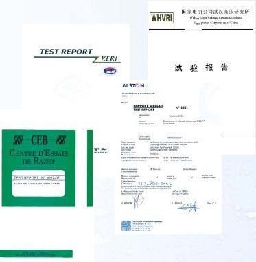
In order to meet both the requirements of existing legislation and the demands of the domestic and international markets,Duval Messien has conducted extensive research and rigorous testing in perfecting the Satelit 3 lightning conductor (in accordance with the NF C 17-102 standard).
Trials of Satelit 3 lightning conductors have been conducted in various countries by independent, approved laboratories, as well as in France at the Bazet Test Centre (COFRAC approved) under Lloyd’s Register control (the certifier European body).
The SATELIT 3 protection radii(Rp) are calculated according to the formula defined in the French Standard NF C 17-102 dated july 1995 according to the lightning conductor triggering advance (ΔT), its height (h) and the level of protection required (Np).
Satelit 3 RANGE
| Protection radii (m) |
| Type SATELIT3 |
h = tip height (m) |
| 2 |
3 |
4 |
5 |
6 |
10 |
15 |
20 |
45 |
60 |
| Level 1 |
| Satelit 3-25 |
17 |
25 |
34 |
42 |
43 |
44 |
45 |
45 |
45 |
45 |
| Satelit 3-45 |
26 |
38 |
50 |
63 |
63 |
64 |
65 |
65 |
65 |
65 |
| Satelit 3-60 |
32 |
48 |
64 |
79 |
79 |
79 |
80 |
80 |
80 |
80 |
| Level 2 |
| Satelit 3-25 |
23 |
34 |
46 |
57 |
58 |
61 |
63 |
65 |
70 |
70 |
| Satelit 3-45 |
34 |
48 |
64 |
81 |
81 |
83 |
85 |
86 |
90 |
90 |
| Satelit 3-60 |
40 |
59 |
78 |
97 |
97 |
99 |
101 |
102 |
105 |
105 |
| Level 3 |
| Satelit 3-25 |
26 |
39 |
52 |
65 |
66 |
69 |
72 |
75 |
84 |
85 |
| Satelit 3-45 |
36 |
50 |
72 |
89 |
90 |
92 |
95 |
97 |
104 |
105 |
| Satelit 3-60 |
44 |
65 |
87 |
107 |
107 |
109 |
111 |
113 |
119 |
120 |
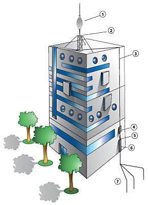
PRINCIPLE OF A TYPICAL INSTALLATION
One or several Satelit 3 lightning conductors are required to protect a structure or a zone, depending on the surface area to be protected and the level of protection required.
Each Satelit 3 lightning conductor is located on a high spot so as to clearly dominate the building, zone or structure to be protected (at least 2 meters). The choice of the model is a function of the required performance (see page 4).
Each Satelit 3 lightning conductor is connected directly to earth by one or several standard down conductors. All metal masses located inside the security distance must be connected equipotentially.
In accordance with the standards in force, the down part of each conductor must be equipped with a test joint, a protective sheath and eventually a lightning strike counter.
The design of the earthing system must be suited to the lightning current to be dissipated. It must be equipotential with the earth connections of the electrical installations. electrical installations.
1. ESE Satelit 3
2. Extension mast
3. Down conductor
4. Test joint
5. Protective sheath
6. Earthing system
TeleTester-S3
To ensure maximum safety and ease of use, the Early Streamer Emission lightning conductor Satelit 3 can be tested
remotely, via radio signals, with the new TeleTester-S3.
The Satelit 3 has an on-board transmitter using a standard frequency and transmitting a signal every 90 seconds to confirm the correct operation of the lightning conductor’s electronics, including the polarisation of its tip. The TeleTester-S3 receives the information transmitted by the Satelit 3 and emits an audible signal confirming that the installation is fully functional.
THIS CHECK CAN BE PERFORMED UP TO A DISTANCE OF 50 M BETWEEN THE Satelit 3 AND THE TeleTester-S3.
- LIMIT THE NUMBER OF ON-SITE 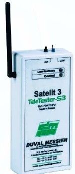 INTERVENTIONS. INTERVENTIONS.
- RAPIDLY CHECK THE Satelit 3 LIGHTNING CONDUCTOR’S CONDITION AND ITS CORRECT OPERATION.
- AVOID RECOURSE TO COSTLY AERIAL EQUIPMENT ON SITES WITH DIFFICULT ACCESS.
- GUARANTEE OPTIMUM PROTECTION AGAINST THE EFFECTS OF LIGHTNING, BY ITS SIMPLICITY OF
OPERATION.
- ENABLE MAINTENANCE INTERVENTIONS TO BE RAPIDLY DEPLOYED.
TeleTester-S3 CHARACTERISTICS
CASING: ABS 170 mm x 85 mm x 34 mm (IP54)
WEIGHT: 200 gr
OPERATING FREQUENCY: standard
POWER SUPPLY: 9 volts batteries, PP3 type
|